Group assignment
" Probe an input device's analog levels and digital signals". That was what we are required to do as a group for this week which we couldn't do as the tea is not allowed to gather in the lab due to make social distancing.
Individual assignemnt
Input devices i've used:
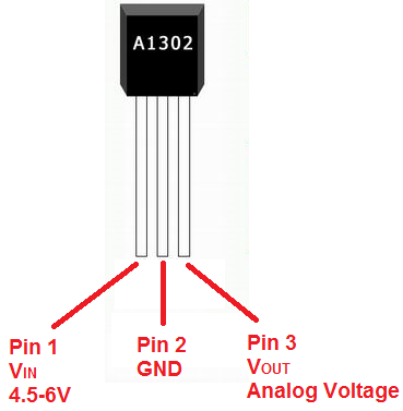
Hall effect sensor: it's better to use but in the end i've used the puzzle parts as a short cercuit input to send the signal
Sensor data sheet
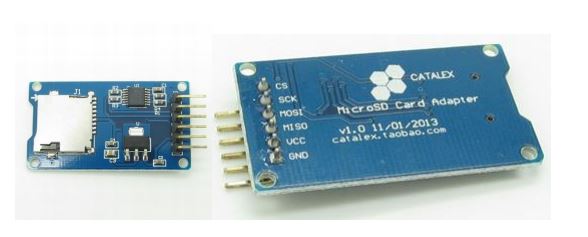
SD card module: I've used this module to put the recorded voices files on the card and connect it to it to be the other input device
Module data sheet
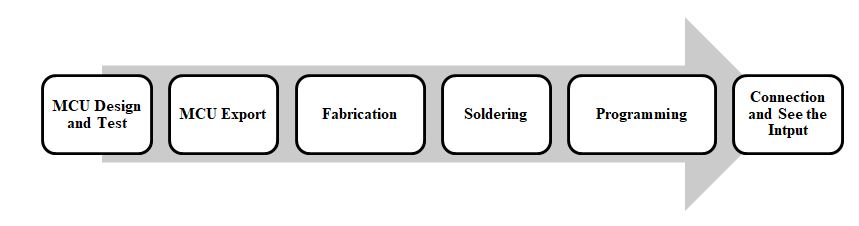
MCU design
In the early beginning of this assignment I memorized the experience from the last assignment of EAGLE software. I used it as it was helpful, suitable, time-saving, and easy to use software.
In this phase I designed the microcontroller board in the flow of:
- Search and build a background
- Collect needed data to assure good design
- Select appropriate design among different ones
- Put the components in the schematic mode in EAGLE software
- Connect them in a rough outline in the same schematic view
- Check overall connection and design
- Go to board view to check the paths and PCB design
- Adjust and develop the full board design with the traces and connecting nodes
- Test the wellness of connections using error tool(DRC/ERC)
Firstly,
I was learning some basics and advanced concepts in eagle to be able
to design the needed circuit on it before implementation
I chose to made my final project circuit in this assignment, So that what you gonna find here in the end, The output is a voice
.
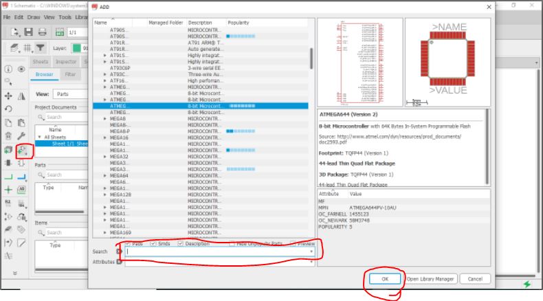
From "Add part" open the list of components(little arrow beside the botton opens the recent components opened), Also you can search for a specific component(But make sure iy's the exact name in the list if not won't appear in search results.
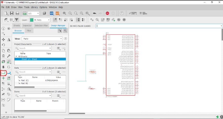
Select "Net" to start connect the components togather"
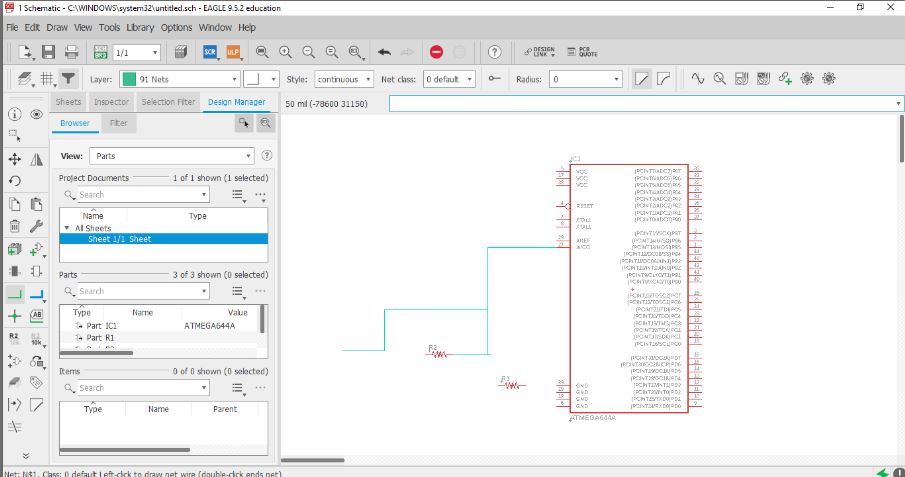
Add more, Connect more and make sure from pollarity for each part (resistor dosen't has polarity but other components have, So stay focus on this)
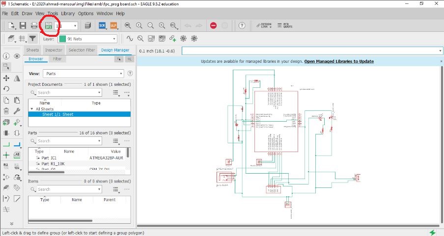
After finishing your circuit connections, check by looking for all connection, Polarity (as we said before) and make sure nothing forgotten, Then let's move to another view from this up left botton from Schematic view to Board view.
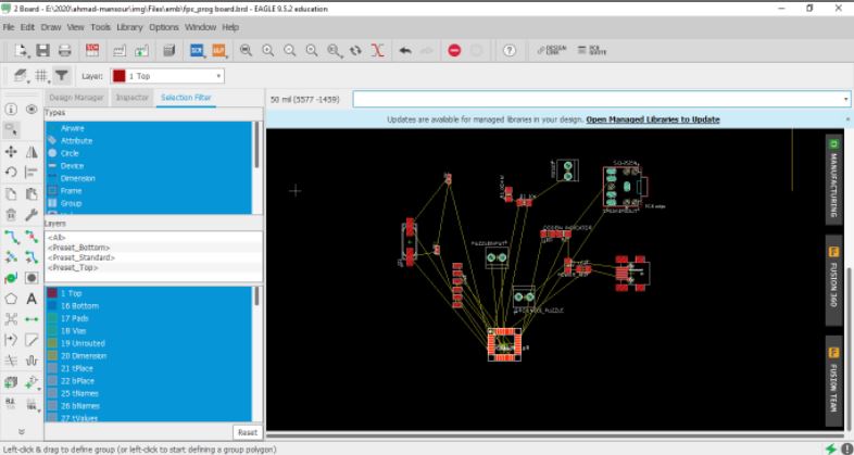
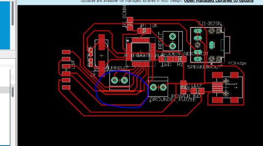
Usually you will find a very messay order for the components, So organize them as much you can based on the connections between components and your general vission for the final result.
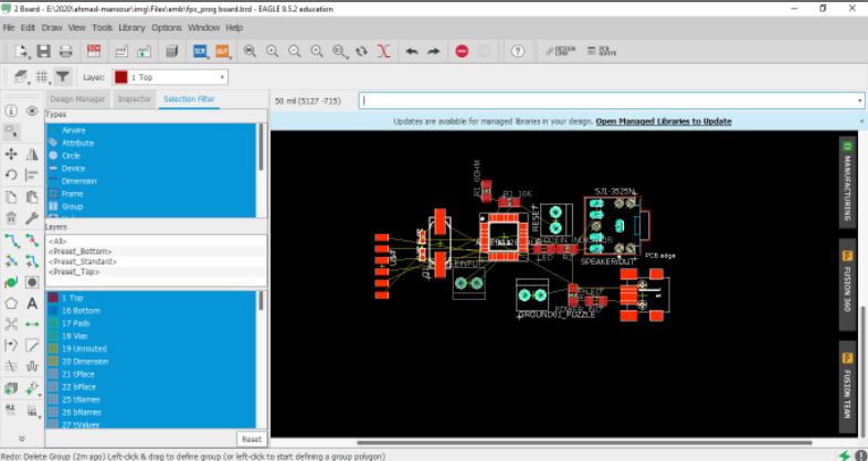
For example here in organizing i've put the resistor and capasitor which connected to microcontroller besid the pins will connect, the jack plug and poer plug in the edge of the circuit.
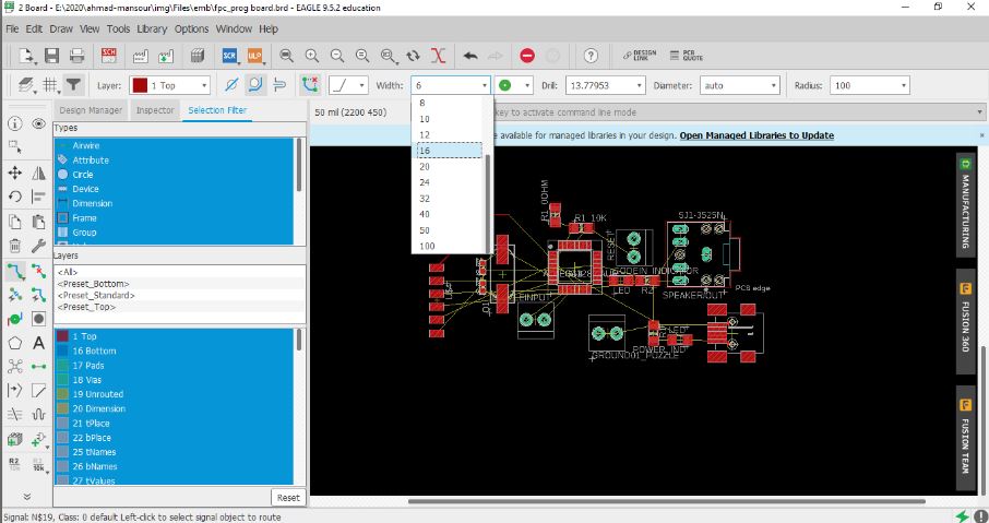
Then select the width of paths i will connect the components with, from 6mill to more than 100 mill( based on the size of the whole circuit, Components size and the cutting tool you can use in the fabrication
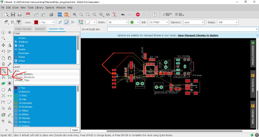
"route airwirw" botton use it to draw the connections as you want, or use Auto routing(but from my humble experience in this and some recommendations from my colleages, Auto routing isn't good enogh to get you the best result you need)

I can tell you a small tips for routing but i see it's very important:Start with connecting everything connected except VCC and ground, Leave then to the end beacuse they made alot of confusion in connections if you started with
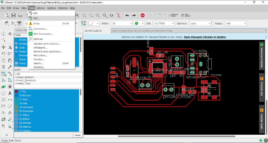
Now lets test the paths if it will work will or we need to adjust anything of route or the width.
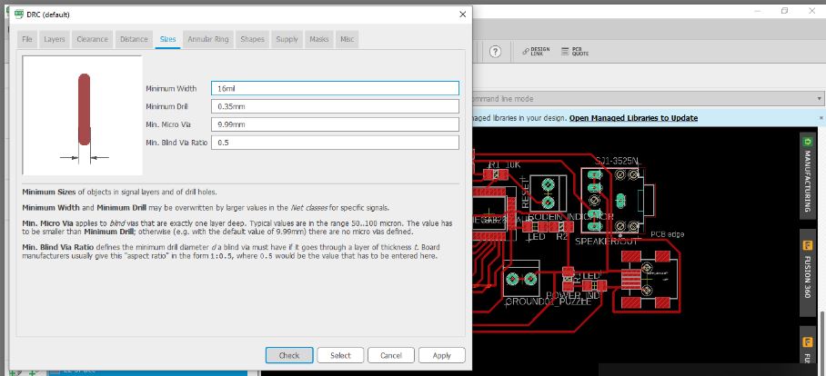
Set the width you use, Tool width you will use, Then let's test.
Be careful from overlapped paths
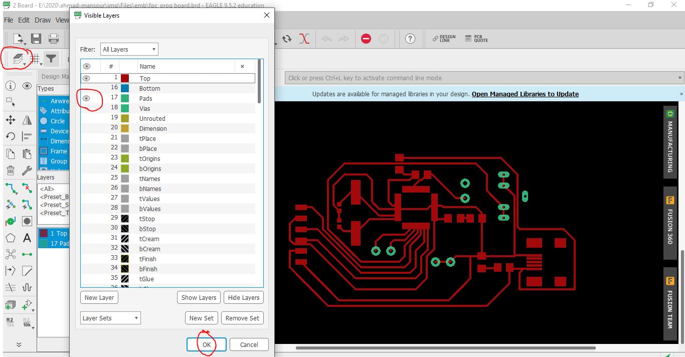
Open layers management list, Hide and appear layers to get the result of only traces and nodes appear, Then press OK.
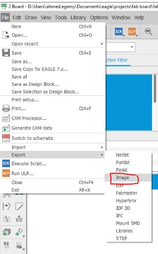
Emporting the circuit picture to implement
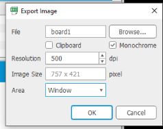
Make monochromatic(black&white), 500dpi and window to capture only the window view you open
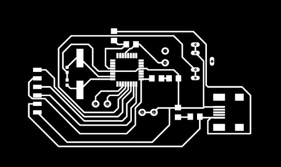
Final result, Now the impletation software can see the traces and nodes to fabricate.
PNG image
Schematics eagle file
Board eagle file
You can find the Fabrication, soldering and programming processes here to get the design alive here
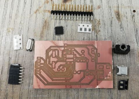
Fabricated board, With components to solder
Get an Arduino and connect it with the board, VCC connected to 5V and GND connected to GND.
Slave reset: 10
MOSI: 11
MISO: 12
SCK: 13
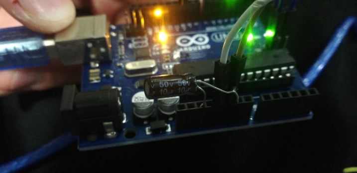
Connect 10uf capacitor to reset and GND to prevent the arduino from resetting after burnining the code(find the full details in the tutorial above)
Prepare
my own board by burn on it the bootloader to be ready for
programming
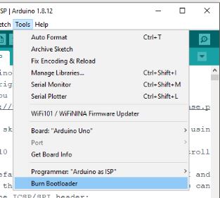
Importatnt:Make this step when you open a new and empty window of Arduino
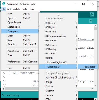
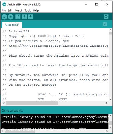
Uploaded
Arduino ISP code on the Arduino board to make it a programmer.
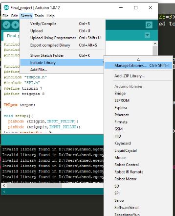
Mangeme library from Arduino
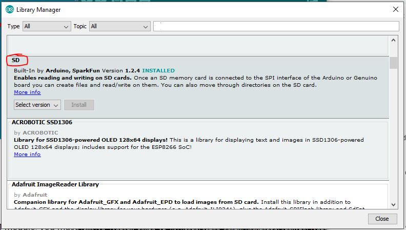
Adding the library from Library manager
Library file
Then I've uploaded my code on board
#include
#include
#include

#include "SD.h"
#define SD_ChipSelectPin 4
#include "TMRpcm.h"
#include "SPI.h"
#define trigpin 7
#define trigopin 8

TMRpcm tmrpcm;

void setup(){
  pinMode (trigpin,INPUT_PULLUP);
  pinMode (trigopin,INPUT_PULLUP);
tmrpcm.speakerPin = 9;
Serial.begin(9600);
if (!SD.begin(SD_ChipSelectPin)) {
Serial.println("SD fail");
return;
}


}
int flag=0;
int flag1=0;

void loop(){
  int sp;
  int sp1;
  sp=digitalRead(trigpin);
    sp1=digitalRead(trigopin);
      if (sp==LOW&&flag==0) {
     tmrpcm.setVolume(5);
tmrpcm.play("diags.wav");
delay (5000);
flag=1;
  }
  else if (sp1==LOW&&flag1==0) {
     tmrpcm.setVolume(5);
tmrpcm.play("Africa.wav");
delay (5000);
flag1=1;
  }
  else if (sp==HIGH&&sp1==HIGH){
    flag=0;
    flag1=0;
    delay (500);
    }

  }
Now lets test it
Arduino code source
Done
- Testing the input devices efficency.
s
New Learned
- Diferance between input and output devices.
- How to measure an input.
Enjoyed with
- Exploring diferent input devices.
- Programming.
- Testing and seeing the input works.
Firstly, I was learning some basics and advanced concepts in eagle to be able to design the needed circuit on it before implementation
I chose to made my final project circuit in this assignment, So that what you gonna find here in the end, The output is a voice
.
PNG image
Schematics eagle file
Board eagle file
You can find the Fabrication, soldering and programming processes here to get the design alive here
Get an Arduino and connect it with the board, VCC connected to 5V and GND connected to GND.
Slave reset: 10
MOSI: 11
MISO: 12
SCK: 13
Prepare my own board by burn on it the bootloader to be ready for programming
Uploaded Arduino ISP code on the Arduino board to make it a programmer.
Then I've uploaded my code on board
#include#include #include #include "SD.h" #define SD_ChipSelectPin 4 #include "TMRpcm.h" #include "SPI.h" #define trigpin 7 #define trigopin 8 TMRpcm tmrpcm; void setup(){ pinMode (trigpin,INPUT_PULLUP); pinMode (trigopin,INPUT_PULLUP); tmrpcm.speakerPin = 9; Serial.begin(9600); if (!SD.begin(SD_ChipSelectPin)) { Serial.println("SD fail"); return; } } int flag=0; int flag1=0; void loop(){ int sp; int sp1; sp=digitalRead(trigpin); sp1=digitalRead(trigopin); if (sp==LOW&&flag==0) { tmrpcm.setVolume(5); tmrpcm.play("diags.wav"); delay (5000); flag=1; } else if (sp1==LOW&&flag1==0) { tmrpcm.setVolume(5); tmrpcm.play("Africa.wav"); delay (5000); flag1=1; } else if (sp==HIGH&&sp1==HIGH){ flag=0; flag1=0; delay (500); } }